
 SHOW MENU
Penny Red Die I Plating Tool – Instructions
QUICK LINKS
The general principle of the Fisher-Brown method uses the fact that the check letters in the corner squares of the line engraved stamps were produced using hand punches. That means their positions vary from plate to plate, thus providing a primary basis for plating these issues.
For the 1d Red Die I, four measurements (two for each check-letter) have been made for all plates as shown below:
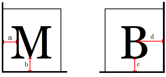
- "a" – distance from outer (West) frame of left square to left check-letter
- "b" – distance from lower (South) frame of left square to left check-letter
- "c" – distance from lower (South) frame of right square to right check-letter
- "d" – distance from outer (East) frame of right square to right check-letter
General Principles

The online version is a development of the original physical system, which used a transparent plastic gauge supplied with the books. This was slid over the stamp in the manner of a perforation gauge, and measurements made with the aid of a strong magnifying glass (see illustration at right).
The general idea of both versions is that the numbered "baseline" is positioned on the frame line of the corner square, and moved along it until the sloping "gauge line" touches a standard "reference point" on the letter. The actual measurement is then read off from the point on the numbered line opposite the centre of the letter
As this procedure was obviously somewhat approximate, measurements can have a "-" or "+" after the number to indicate they are just to one side of the whole number. So the possible measurements in order are:
0, 1-, 1, 1+, 2-, 2, 2+, 3-, 3, 3+, 4-, 4, 4+, ... 17
The E-Gauge extends this idea to a computerised version, using an image with the lines on a transparent background that can be moved over 800dpi scans of the stamp, avoiding the need for a magnifying glass.
The latest version simplifies this further, by also allowing you to measure distances directly on a scan of a stamp as a number of pixels, using a computer graphics program of your choice, and using this figure instead.
Reference and Measurement Points
The reference point (also called datum point) is the point on the letter that is used to position the sloping gauge line. In most cases this is on the body of the letter, ignoring the serifs. The measurement point is simply the point on the numbered baseline opposite the centre of the letter – in other words, not opposite the point of contact (to avoid doubt with tilted letters where the gauge line may appear to touch all along the side).
The illustrations below show the reference points for each possible letter, together with the position of the sloping gauge lines when lined up correctly:
 = sloping gauge lines
 = measurement scale baseline placed on edge of corner square
 = position of reference point on scale
 = position of measurement point on scale
 = reference and measurement points coincide
 = position on measurement scale baseline where measurement is read

Left Check Letters (A-T)

Right Check Letters (A-L)
The "E-Gauge"
To use the E-Gauge, you will need to upload a scan of your stamp at a resolution of 800dpi. This is the closest standard scanner resolution to the physical gauge, which measures to 1/30 mm, corresponding to 762dpi.The image should be cropped closely to the margins of the stamp, and the bottom frame line should be as level as possible in the scan. Some scanners offer an automatic "straighten" (which may work well, or may not). The better graphics programs (e.g. Photoshop or Paint Shop Pro) will usually have a tool that lets you place a guide line along the base and then rotate the image to make that line horizontal. Alternatively, any reasonable graphics program will allow you to rotate an image by a specified angle (though it may take a little trial and error to find the correct one!).
After an image is uploaded the E-Gauge image can be dragged into position with the mouse (in the usual way – click on it with the left mouse button, then hold the button down while you move the mouse). The gauge should be positioned with the inner edge of the baseline resting on the inner frame line of the letter square. The E-Gauge differs slightly in appearance from the original physical gauge – the sloping gauge line is "stepped" rather than being a solid line at an angle (to give a definite break point to judge the reading).
Note that since the 762dpi and 800dpi scales are not identical, there is a slight error which increases as the numbers do, though this is only very noticeable on the a and d measurements. To compensate, two alternative gauge lines are included for these, so you can use one for 0-8 measurements and the other for 8-17.
Here are some examples, one for each measure a, b, c and d:
 |
Set the inside edge of the broken B(aseline) to the inside edge of the letter square. Move the gauge vertically to align the stepped cursor to the R(eference) point on the letter. Set the cursor so that the outside edge of a step corresponds to the reference point at the centre of the step. Here the value on the gauge is 11, however ... ... the M(easurement) is taken corresponding to the centre of the letter. The recorded a value here is therefore 11-. Using the same colour code for the reference and measurement points, examples for the b, c, and d values are given below. |
|
The reference point at the tail of the letter "Q" corresponds to 3+ on the gauge, but the recorded b value is 4-, measured at the centre. |
 |
 |
The reference and measurement points coincide at the base of the "C" to give a c value of 3-. |
|
The d value here is on the cusp of 4-/3+. It is perhaps unfortunate that Fisher-Brown did not exclude serifs in their entirety. |
 |
The Pixel Counting Method
The latest version of the plating tool also allows you to get the Fisher-Brown values by pixel counting on a scanned digital image of the stamp. The method is more precise than the E-Gauge, as it is free from any scaling approximation. It simplifies things further by using the measurement at the reference point as the value to be entered. (The tool includes a correction table to automatically work out and use what the value at the centre of the check letter would have been so that it converts to the correct Fisher-Brown value. Note that the corrections differ slightly between Alphabet I and Alphabet II, because of the size of the letters, and so the Fisher-Brown values for a given alphabet and pixel measurement may occasionally differ by one step.) It is also unnecessary to work on a close-cropped image of a single stamp; measurements may be made on a unit within a strip or block of stamps.
Image Quality
You should still scan at as high a resolution as possible – of the standard scanner resolutions, 800dpi is a good minimum. Higher resolutions will enable more accurate measurements, to a practical upper limit of 2400dpi. (This refers to scanner "optical" resolutions – i.e. what your scanner is physically capable of. Many scanners offer higher "computed" resolutions, but those effectively just enlarge a smaller scan and so don't give any greater precision. Note that digital camera photographs are generally out-of-square and of variable dpi, so are unsuitable unless taken on a professional photographic set-up.)
It is however possible to use lower resolution images if that is all that is available (such as for example pictures shown in an eBay listing), although this will naturally reduce the accuracy.
For the best image quality the stamp should be placed directly on the scanner glass, rather than inside a mount or stockcard. It should be positioned as straight as possible, aiming for a tilt of not more than ½°. Most graphics programs have straightening routines that can help here. If it is necessary to scan with the stamp mounted in a philatelic card, try to place the top of the stamp under the polyester film, so that if possible the bottom of the stamp remains in direct contact with the glass. This ensures that the check letters and their squares are in sharp focus.
Save the image either in JPEG format set to the highest quality setting, or in a low loss format such as PNG or TIFF. Use a low loss format if the image requires straightening and/or sharpening (or if a letter is obscured by a postmark, and you plan to try to see it using channel splitting techniques in retroReveal or an image editor).
Using Common Graphics Programs to Get the Measurements
In Corel Paint Shop Pro there are at least 2 options:
- Open the crop box. Align one side of the box on the baseline and move the opposite side of the box to align with the reference point, as shown in the manuals. Read & record the gap in pixels directly from the display showing the size of the box. Do this in sequence for the a, b, c, and d values.
- Open the "pick" tool. For the a and d values, set the arrow or cross-wire to the reference point on the check letter. Record the pixel x-coordinate. Move the arrow horizontally (keeping the y-coordinate constant) and measure the x-coordinate at the baseline. The difference between the two numbers is the a or d value. For the b and c values the process is reversed: measure the differences in the y-coordinates keeping the x-coordinate constant for each pair of data.
In Adobe Photoshop:
Open the ruler and select the move arrow. Zero the ruler to the baseline. Point the arrow to the reference point and note the value at the ruler. For measurements on 800dpi to 1200dpi images it may be necessary to magnify the image to expand the intervals of the ruler. The ruler is pseudo-analogue, so record each value to the nearest whole pixel.
Converting Pixel Counts to Fisher-Brown Values
Just select "pixels" from the "Measurements are:" options and enter the resolution of the image in the box that appears, then enter the pixel counts in the a, b, c, and d boxes. The corresponding Fisher-Brown values are displayed next to each box as a sanity check – Alphabet I values on the left, Alphabet II values on the right. Then click "Search" to show a shortlist of possible plates in the normal manner.


